
Connecting a Peugeot car radio with an electrical tester requires understanding a specific feature of the brand: most recent models use a proprietary connector, rather than a standard ISO double plug. This specificity radically changes the way to test the wires and connect an aftermarket device.
Proprietary Peugeot connector or ISO plug: what the electrical tester actually measures
On many recent Peugeots (308 II, 508, 2008, 3008), the wiring harness behind the radio slot is not a pair of standard ISO connectors. It is a Quadlock or MOST type manufacturer connector that combines power, audio signals, and sometimes network data into a single block.
When you bring your electrical tester close to this connector, you will not find the usual arrangement of yellow (permanent), red (accessory), and black (ground) wires. The pins are arranged according to a layout specific to Peugeot/Citroën. Testing this connector directly without an adapter exposes you to two risks: identifying a CAN-Bus data wire as a power wire, or sending current to a communication pin.
A Peugeot/Citroën to ISO adapter solves this problem by matching each manufacturer pin to its standardized ISO equivalent. Specifically, you test on the ISO adapter side, not on the manufacturer harness. The electrical tester is then used to confirm the presence of voltage on the yellow and red wires of the adapter, and the continuity of the ground on the black wire.
Following a Peugeot car radio connection tutorial with the ISO color scheme facilitates this step, as the colors of the adapter comply with ISO 10487 standards.
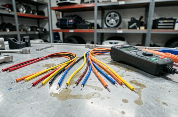
ISO wire table and multimeter test points
Once the adapter is connected on the vehicle side, the wires to be tested follow the ISO convention. The table below summarizes the main wires, their function, and the expected value on the tester.
| ISO Wire Color | Function | Expected Measurement (tester/multimeter) |
|---|---|---|
| Yellow | Permanent power (memory) | DC voltage present with ignition off |
| Red | Accessory power (with ignition) | Voltage present only with ignition on |
| Black | Ground | Continuity with the body |
| Blue | Electric antenna control | Voltage present when the car radio is on |
| Gray, white, green, purple | Speaker outputs (pairs +/-) | No DC voltage, audio signal in operation |
The “expected measurement” column indicates what the tester should display at each step. If the yellow wire shows no voltage with the ignition off, the problem lies upstream, at the fuse or vehicle harness.
Difference between basic tester and multimeter
A basic electrical tester (like a LED screwdriver tester) confirms the presence or absence of voltage. It is sufficient to check the yellow and red wires. However, it does not measure the exact voltage value or the continuity of a circuit.
A multimeter set to DC voltmeter mode allows you to read the actual voltage and detect an abnormal drop that would indicate a poor connection or a worn fuse. The multimeter remains the most reliable tool for diagnosing a power issue on a Peugeot car radio.
Peugeot CAN-Bus Network: wires not to test under voltage
Peugeots equipped with a multimedia system connected to the CAN-Bus network add a layer of complexity absent in older vehicles. Steering wheel controls, display on the dashboard, and sometimes air conditioning pass through CAN-Bus data wires that run alongside the power wires.
Applying the tip of a tester to a live CAN-Bus wire can disrupt communication between control units. On some models, this triggers faults stored in the intelligent service box (BSI). These faults do not always clear spontaneously and may sometimes require diagnostic access.
How to identify CAN-Bus wires before testing
CAN-Bus wires typically come in twisted pairs. Their gauge is finer than that of power wires. On the ISO adapter, they are not present: the adapter separates power and audio from the rest.
- Ensure you are only testing the wires coming from the ISO adapter, never directly on the vehicle’s Quadlock or MOST connector
- If your Peugeot has steering wheel controls, a dedicated Canbus box must be interposed between the adapter and the car radio to convert signals
- Never probe a pin whose function you do not know with a live tester: consult the pinout diagram specific to your model
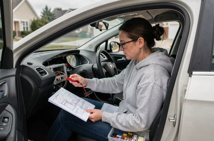
Common mistakes when connecting Peugeot car radio with tester
The most common mistake is reversing the yellow and red wires. The car radio turns on, but the memory of stations and the clock resets every time the ignition is turned off. The electrical tester allows you to distinguish between these two wires: the yellow retains its voltage when the engine is off, while the red loses it.
Another frequent mistake concerns the ground. Connecting the black wire to a poorly cleaned or oxidized body point creates parasitic resistance. The tester in continuity mode should indicate a value close to zero between the black wire and a clean ground point. If the value is high, scrape the metal or use another mounting point.
- Yellow wire on red (and vice versa): memory loss or car radio that stays on with the ignition off and drains the battery
- Insufficient ground: audio noise, intermittent cuts, car radio that restarts by itself
- Forgetting the blue antenna wire: very weak or nonexistent radio reception, often mistaken for a faulty car radio
- Direct testing on the Quadlock connector without an adapter: risk of short circuit or CAN-Bus disruption
Connecting a Peugeot car radio with an electrical tester is based on a simple principle: always work on the ISO adapter side, never directly on the proprietary connector. This precaution avoids wiring errors and protects the vehicle’s electronic network. A multimeter costing a few dozen euros and a Peugeot/Citroën to ISO adapter make up the minimal duo to carry out the operation without unpleasant surprises.